Dell OptiPlex GX60 Bedienungsanleitung
Stöbern Sie online oder laden Sie Bedienungsanleitung nach Computers Dell OptiPlex GX60 herunter. Dell OptiPlex GX60 User Manual Benutzerhandbuch
- Seite / 181
- Inhaltsverzeichnis
- FEHLERBEHEBUNG
- LESEZEICHEN
- Advanced Features 1
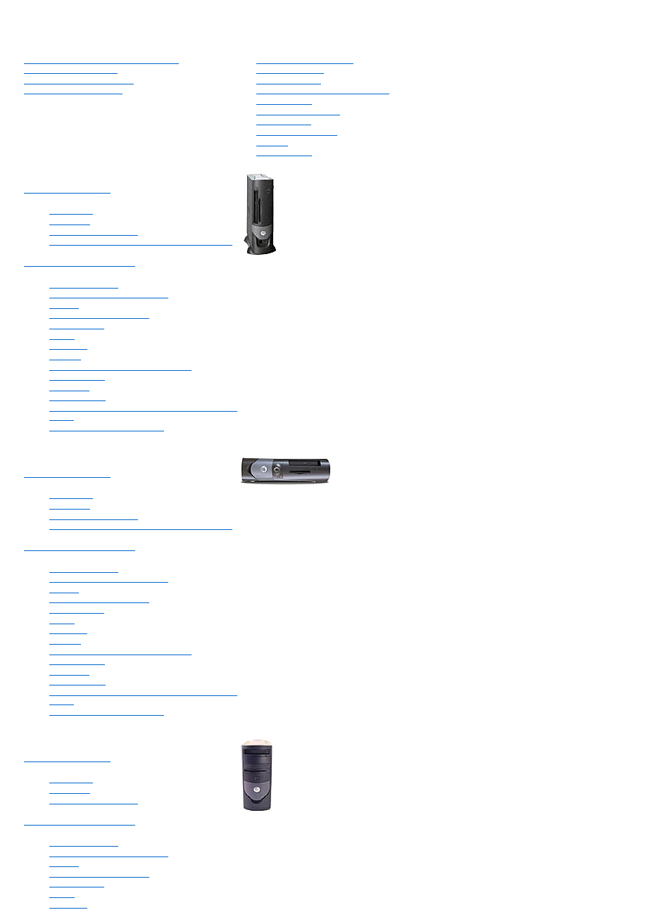
- Small Form-Factor Computer 1
- Small Desktop Computer 1
- Small Mini-Tower Computer 1
- Notes, Notices, and Cautions 2
- Abbreviations and Acronyms 2
- Additional Information 3
- Manageability 5
- Password Protection 6
- Assigning a System Password 7
- Typing Your System Password 7
- Setup Password 8
- Power Button 10
- Power Management 10
- Security 11
- System Setup 12
- Boot Sequence 13
- System Setup Options 14
- Advanced Troubleshooting 16
- Dell Diagnostics Main Menu 17
- Creating a Restore Point 18
- Reinstalling Microsoft 19
- Windows 19
- Reinstalling Windows XP 20
- Before You Begin 21
- Reinstalling Windows 2000 21
- Windows 2000 Setup 22
- Windows XP 22
- Windows 2000 23
- Battery 24
- Chassis Intrusion Switch 28
- Cleaning Your Computer 31
- Control Panel 33
- Replacing the Control Panel 35
- Closing the Computer Cover 38
- Ergonomic Computing Habits 40
- Operating System CD 43
- Getting Help 44
- Technical Support Service 45
- Problems With Your Order 46
- Product Information 46
- Before You Call 46
- Contacting Dell 47
- Glossary 55
- I/O Panel 61
- Replacing the I/O Panel 63
- Memory 64
- Removing Memory 66
- Power Supply 67
- Replacing the Power Supply 69
- DC Power Connectors 69
- DC Power Connector P1 70
- DC Power Connector P2 70
- DC Power Connector P3 71
- DC Power Connector P6 72
- DC Power Connector P5 73
- DC Power Connector P7 75
- Regulatory Notices 76
- IC Notice (Canada Only) 77
- CE Notice (European Union) 77
- VCCI Notice (Japan Only) 78
- Class B ITE 79
- Class A Device 79
- Class B Device 80
- BSMI Notice (Taiwan Only) 81
- ENERGY STAR®Compliance 82
- System Board 83
- SAFETY: General 85
- SAFETY: Battery Disposal 87
- CD/DVD Drive 100
- Installing a CD/DVD Drive 101
- PCI Cards 103
- Removing a PCI Card 105
- Serial Port Adapters 106
- Adding and Removing Parts 109
- Processor 110
- About Your Computer 113
- Inside Your Computer 114
- Cable Colors 115
- IDE Drive Addressing 118
- Connecting Drive Cables 118
- Hard Drive 119
- Installing a Hard Drive 120
- Front-Panel Inserts 122
- Floppy Drive 122
- Installing a Floppy Drive 123
- Back View 138
- Back to Contents Page 140
- Adding a Second Hard Drive 145
- Removing a CD/DVD Drive 151
- Installing the Processor 161
- Solving Problems 164
- Diagnostic Lights 165
- Drive Problems 166
- Error Messages 167
- Keyboard Problems 168
- Memory Problems 169
- Mouse Problems 170
- Network Problems 170
- Power Problems 170
- Printer Problems 171
- Sound and Speaker Problems 172
- Video and Monitor Problems 172
- Wet Computer 173
- Technical Specifications 175
- System Board Components 178
- Installing a TAPI Sound Card 179
- Warranty and Return Policy 181
Inhaltsverzeichnis
Dell™OptiPlex™GX60SystemsUser'sGuide Documentation for Your Computer Finding Information for Your Computer Technical Specifications System B
7. Open the computer cover. 8. Replace the PSWD jumper plug. 9. Close the computer cover and reconnect the computer and devices to electrical
After you open and close the cover, the chassis intrusion detector, if enabled, causes the following message to appear on the screen at the next comp
Installing a CD/DVD Drive 1. Unpack the drive and prepare it for installation. Check the documentation that accompanied the drive to verify th
6. If you are installing a drive that has its own controller card, install the controller card in a card slot. 7. Check all cable connections,
Back to Contents Page PCI Cards and Serial Port Adapters Dell™OptiPlex™GX60SystemsUser'sGuide PCI Cards Serial Port Adapters You
2. If you are installing a new card, remove the filler bracket to create an empty card-slot opening. If you are replacing a card that is already i
7. Reconnect any cables that you removed in step1 in the previous procedure. 8. Connect any cables that should be attached to the card. Se
4. If necessary, disconnect any cables connected to the card. 5. Grasp the card by its top corners, and ease it out of its connector. 6. If yo
7. Close the computer cover, reconnect the computer and devices to their electrical outlets, and turn them on. After you open and close the
After you open and close the cover, the chassis intrusion detector, if enabled, causes the following message to appear on the screen at the next compu
Back to Contents Page Adding and Removing Parts Dell™OptiPlex™GX60SystemsUser'sGuide Opening the Computer Cover 1. Perform an orderly co
l Shutdown. This sleep state removes all power from the computer except a small auxiliary amount. As long as the computer remains connected to an e
Back to Contents Page Processor Dell™OptiPlex™GX60SystemsUser'sGuide 1. Follow the procedures in "Before You Begin." 2.
8. Unpack the new processor. If any of the pins on the processor appear to be bent, contact Dell for instructions on obtaining technical a
If you are installing a processor replacement kit from Dell, return the processor to Dell in the same package in which your replacement kit was sen
Back to Contents Page About Your Computer Dell™OptiPlex™GX60SystemsUser'sGuide Front View Back View Inside Your Computer Attachin
Inside Your Computer 1 parallel connector Connect a parallel device, such as a printer, to the parallel connector. If you have a USB
Cable Colors Attaching and Removing the Computer Stand The computer can be used in either a vertical or horizontal position. To use the
To remove the computer stand: 1. Turn the computer over so that the stand is at the top. 2. Loosen the thumbscrew and lift the stand away. 3.
Back to Contents Page Small Form-Factor Computer Dell™OptiPlex™GX60SystemsUser'sGuide Back to Contents Page
Back to Contents Page Drives Dell™OptiPlex™GX60SystemsUser'sGuide General Installation Guidelines Hard Drive Front-Panel Inserts Fl
Most interface connectors are keyed for correct insertion; that is, a notch or a missing pin on one connector matches a tab or a filled-in hol
Padlock Ring and Security Cable Slot Use one of the following methods to secure your computer: l Use a padlock alone or a padlock and looped securi
2. Press in on the tabs on each side of the drive and slide the drive toward the I/O panel and remove it from the computer. Installing a Hard
3. Install the hard drive into the computer by gently sliding the drive into place until you hear it securely click. 4. Connect the power and ha
Front-Panel Inserts If you are installing a new floppy or CD/DVD drive rather than replacing a drive, remove the front-panel insert. Floppy Dri
b. To release the floppy-drive cable from the connector, slide the lever until it is fully extended, and then lift the cable away. 6. Remove
4. Attach the power cable to the interposer board on the floppy drive. 5. Attach the CD/DVD drive cable and the power cable to the CD/DVD driv
12. Verify that your computer works correctly by running the Dell Diagnostics. CD/DVD Drive Removing a CD/DVD Drive 1. Follow the procedure
2. Unpack the drive and prepare it for installation. Check the documentation that accompanied the drive to verify that the drive is configured for
10. Update your configuration information by setting the appropriate Drive option (0 or 1) under Drives: Secondary to Auto. See "Drive Configura
Back to Contents Page PCI Cards and Serial Port Adapters Dell™OptiPlex™GX60SystemsUser'sGuide PCI Cards Serial Port Adapters Y
3. If you are installing a new card, remove the filler bracket to create an empty card-slot opening, then continue with step5. 4. If you are re
Boot Sequence This feature allows users to change the sequence of devices from which the computer boots. Option Settings l Normal — (Available
10. Close the computer cover, reconnect the computer and devices to their electrical outlets, and turn them on. After you open and close the cov
Serial Port Adapters Installing a Serial Port Adapter 1. Follow the procedures in "Before You Begin." 2. Raise the retention arm.
5. If you are removing the card permanently, install a filler bracket in the empty card-slot opening. If you need a filler bracket, contact Dell.
Back to Contents Page Adding and Removing Parts Dell™OptiPlex™GX60SystemsUser'sGuide Opening the Computer Cover 1. Perform an orderly
Back to Contents Page Processor Dell™OptiPlex™GX60SystemsUser'sGuide 1. Follow the procedures in "Before You Begin." 2.
8. Unpack the new processor. If any of the pins on the processor appear to be bent, contact Dell for instructions on obtaining technical a
If you are installing a processor replacement kit from Dell, return the processor to Dell in the same package in which your replacement kit was sen
Back to Contents Page About Your Computer Dell™OptiPlex™GX60SystemsUser'sGuide Front View Back View Inside Your Computer Front Vi
Back View 1 power connector The connection for the power cable. 2 voltage selection switch (may not be available on all computers) Se
Inside Your Computer Cable Colors On computers with a sound card, the line-in connector is on the card. 8 line-out connector Us
5. Press plus (+) or minus (–) to move a selected device up or down the list. System Setup Options AC Power Recovery — Determines what happens w
Back to Contents Page
Back to Contents Page Small Mini-Tower Computer Dell™OptiPlex™GX60SystemsUser'sGuide Back to Contents Page
Back to Contents Page Drives Dell™OptiPlex™GX60SystemsUser'sGuide General Installation Guidelines Hard Drive Front-Panel Inserts Fl
Most interface connectors are keyed for correct insertion; that is, a notch or a missing pin on one connector matches a tab or a filled-in hole
2. Press in on the tabs on each side of the drive and slide the drive up and out. Installing a Hard Drive 1. Unpack the replacement h
5. Connect the power and hard-drive cables to the drive. 6. Check all connectors to be certain that they are properly cabled and firmly s
1. Check the documentation for the drive to verify that it is configured for your computer. 2. Follow the procedures in "Before You Beg
9. Close the computer cover. 10. Connect your computer and devices to their electrical outlets, and turn them on. See the documentation t
4. From the outside of the computer, pull the insert away from the computer's front panel. 5. Remove the insert from the insert frame by pr
4. Press inward on the two tabs on the sides of the drive, slide the drive upward, and remove it from the floppy-drive bay. Installing a F
Back to Contents Page l Sound — Settings are On (default) or Off. l USB Controller — Settings are On (default) or Off. l USB Emulation — Set
3. Attach the power and floppy-drive cables to the floppy drive. 4. Connect the other end of the floppy-drive cable to the connector labeled DSKT
Removing a CD/DVD Drive 1. Follow the procedures in "Before You Begin." 2. Disconnect the power, audio, and CD/DVD drive cables from th
4. Gently slide the drive into place until the tabs securely click into position. 5. Connect the power, audio, and CD/DVD drive cables to the
computer start-up: ALERT! Cover was previously removed. 12. Reset the chassis intrusion detector by changing Chassis Intrusion to Enabled or Enabl
Back to Contents Page PCI Cards and Serial Port Adapters Dell™OptiPlex™GX60SystemsUser'sGuide PCI Cards Serial Port Adapters YourDe
3. If you are installing a new card, remove the filler bracket to create a card-slot opening, and then continue with step5. 4. If you are replaci
8. Connect any cables that should be attached to the card. See the documentation for the card for information about the card's cable co
2. Press the lever on the card retention arm and raise the retention arm (see step2 in the previous procedure). 3. If necessary, disconnect any
5. Attach the serial adapter cable to the serial port connector on the system board (labeled SER2). 6. Close the computer cover, reconnect t
Back to Contents Page Adding and Removing Parts Dell™OptiPlex™GX60SystemsUser'sGuide Opening the Computer Cover 1. Perform an orderly co
Back to Contents Page Advanced Troubleshooting Dell™OptiPlex™GX60SystemsUser'sGuide Dell Diagnostics Reinstalling Drivers and Utiliti
Back to Contents Page Processor Dell™OptiPlex™GX60SystemsUser'sGuide Removing the Processor Installing the Processor Removing the
6. Pull the release lever straight up until the processor is released. 7. Remove the processor from the socket. Leave the relea
2. Align pin 1 (the imprinted corner) of the processor and pin 1 of the socket. 3. Carefully set the processor in the socket and press it
replacement kit was sent. 8. Reconnect the cooling fan power cable to the FAN connector on the system board. 9. Reconnect the power cable to the 1
Back to Contents Page Solving Problems Dell™OptiPlex™GX60SystemsUser'sGuide Battery Problems Fill out the Diagnostics Checklist as yo
Diagnostic Lights To help you troubleshoot a problem, your computer is equipped with four lights on the back panel labeled "A," "B,&quo
Drive Problems Fill out the Diagnostics Checklist as you complete these checks. CD and DVD drive problems Problems writing to a CD/DVD-RW drive
Error Messages Fill out the Diagnostics Checklist as you complete these checks. If the message is not listed, see the documentation for the operati
Keyboard Problems Lockups and Software Problems boot device. l Enter system setup and ensure that the boot sequence information is correct. No
The computer does not start up The computer stops responding A program stops responding A program crashes repeatedly A solid blue screen a
3. When the boot device list appears, highlight IDE CD-ROM Device and press <Enter>. 4. Select the IDE CD-ROM Device option from the CD boot
Mouse Problems Network Problems Fill out the Diagnostics Checklist as you complete these checks. Power Problems Fill out the Diagnostics Chec
Printer Problems Fill out the Diagnostics Checklist as you complete these checks. Serial or Parallel Device Problems Fill out the Diagnostics C
Sound and Speaker Problems Fill out the Diagnostics Checklist as you complete these checks. No sound from speakers No sound from headphones V
If the screen is blank If the screen is difficult to read Wet Computer Fill out the Diagnostics Checklist as you complete these checks. Ba
Back to Contents Page Technical Specifications Dell™OptiPlex™GX60SystemsUser'sGuide ProcessorPortsMemoryKey CombinationsCompute
Small form-factor computer expansion-card connector one PCI slot; low-profile cards are supported (card size = 6.35 cm [2.5 inches] high by 16.76 cm
Back to Contents Page <Ctrl><Alt><D> launches the hard-drive diagnostics utility during computer start-up Controls and Lights
Back to Contents Page System Board Components Dell™OptiPlex™GX60SystemsUser'sGuide Back to Contents Page 1 floppy drive connector (DSK
Back to Contents Page Telephony Applications Programming Interface (TAPI) Dell™OptiPlex™GX60SystemsUser'sGuide Installing a TAPI-Compli
4. In the System Properties window, click the Hardware tab. 5. Click Device Manager. 6. Right-click the device for which the new driver was in
1. Follow the procedures in "Before You Begin." 2. Install the TAPI-compliant sound card. 3. Connect external audio devices to th
Back to Contents Page Warranty and Return Policy Dell™OptiPlex™GX60SystemsUser'sGuide Dell Inc. ("Dell") manufactures its hardw
1. Click the Start button, point to All Programs→ Accessories→ System Tools, and then click System Restore. 2. Ensure that Restore my computer to
Notes, Notices, and Cautions Abbreviations and Acronyms For a complete list of abbreviations and acronyms, see the Glossary. IfyoupurchasedaDell™
before you installed the new device driver. To reinstall Windows XP, you need the following items: l Dell™Operating System CD l Dell Drivers an
6. When the Regional and Language Options screen appears, select the settings for your location and click Next. 7. Enter your name and organizatio
Booting From the Operating System CD 1. Save and close any open files and exit any open programs. 2. Insert the Operating System CD. If any pr
Conflicts are indicated by a yellow exclamation point (!) beside the conflicting device or a red X if the device has been disabled. 5. Double-click a
Back to Contents Page Battery Dell™OptiPlex™GX60SystemsUser'sGuide Replacing the Battery A coin-cell battery maintains computer configur
6. Close the computer cover, and plug your computer and devices into electrical outlets. 7. Attach the computer stand, if it is used. 8. Af
Back to Contents Page Before You Begin Dell™OptiPlex™GX60SystemsUser'sGuide Recommended Tools Shutting Down Your Computer This section
Back to Contents Page Chassis Intrusion Switch Dell™OptiPlex™GX60SystemsUser'sGuide Replacing the Chassis Intrusion Switch Resetting th
Small Mini-Tower Computer 4. Slide the chassis intrusion switch into its slot and reconnect the cable to the connector on the control panel.
Back to Contents Page Additional Information Dell™OptiPlex™GX60SystemsUser'sGuide Back to Contents Page
3. Press <Alt><b> to restart the computer and implement your changes. Back to Contents Page
Back to Contents Page Cleaning Your Computer Dell™OptiPlex™GX60SystemsUser'sGuide Computer, Keyboard, and Monitor Mouse Floppy Drive CD
2. With a soft, lint-free cloth, gently wipe the bottom of the disc (the unlabeled side) in a straight line from the center to the outer edge of th
Back to Contents Page Control Panel Dell™OptiPlex™GX60SystemsUser'sGuide Removing the Control Panel Small Form-Factor Computer 1. Follo
3. Remove the metal control-panel shield. 4. Remove the screw that holds the control panel to the computer, and remove the control panel. Small
4. If necessary, remove the computer cover screw. 5. Close the computer and remove the computer cover. 6. Remove the screw that secures the con
3. Replace the computer cover and ensure that the two metal hooks and tabs are securely in position. 4. To replace the front mask and ac
Follow the steps in the "Removing the Control Panel" procedure in the reverse order, ensuring that all tabs are secure. Back to Contents Pa
Back to Contents Page Closing the Computer Cover Dell™OptiPlex™GX60SystemsUser'sGuide 1. Ensure that all cables are connected, and fo
Back to Contents Page Documentation for Your Computer Dell™OptiPlex™GX60SystemsUser'sGuide Back to Contents Page
Back to Contents Page Advanced Features Dell™OptiPlex™GX60SystemsUser'sGuide Booting to a USB Device Memory Key 1. Insert the memo
Back to Contents Page Ergonomic Computing Habits Dell™OptiPlex™GX60SystemsUser'sGuide For comfort and efficiency, observe the followi
3. International Organization for Standardization (ISO). ISO 9241 Ergonomics requirements for office work with visual display terminals (VDTs). Genev
Back to Contents Page Finding Information for Your Computer Dell™OptiPlex™GX60SystemsUser'sGuide What are you looking for? FindItHere
Back to Contents Page l Details on my computer configuration l Service contract for my computer l How to reinstall my operating system Opera
Back to Contents Page Getting Help Dell™OptiPlex™GX60SystemsUser'sGuide Technical Assistance Problems With Your Order Product Infor
ftp.dell.com/ Log in as user: anonymous, and use your e-mail address as your password. l Electronic Support Service [email protected] s
Problems With Your Order If you have a problem with your order, such as missing parts, wrong parts, or incorrect billing, contact Dell for customer a
Contacting Dell To contact Dell electronically, you can access the following websites: l www.dell.com l support.dell.com (technical support) l
Bahamas General Support toll-free:1-866-278-6818 Barbados General Support 1-800-534-3066 Belgium (Brussels) International Access Code: 00 Co
Country Code: 420 City Code: 2 Technical Support 0221862727 Customer Care 0221862711 Fax 0221862714 TechFax 0221862728 Swit
To change a jumper setting, pull the plug off its pin(s) and carefully fit it down onto the pin(s) indicated. System Board Jumper Settings L
Sales 2108129800 Fax 2108129812 Grenada General Support toll-free:1-866-540-3355 Guatemala General Support 1-800-999-0136 Guyana General
Korea (Seoul) International Access Code: 001 Country Code: 82 City Code: 2 Technical Support toll-free:080-200-3800 Sales toll-free:080-200-
Switchboard 0206745000 Switchboard Fax 0206744750 New Zealand International Access Code: 00 Country Code: 64 E-mail (New Zealand): nz_te
Country Code: 34 City Code: 91 Technical Support 902100130 Customer Care 902118540 Sales 902118541 Switchboard 902118541 Fax 9021
Back to Contents Page Corporate/Public Sector Sales 01344860456 Uruguay General Support toll-free:000-413-598-2521 U.S.A. (Austin, Texas)
Back to Contents Page Glossary Dell™OptiPlex™GX60SystemsUser'sGuide A B C D E F G H I K L M N O P R S U
cm/sec — centimeters per second Control Panel — Part of the computer console that contains indicators and controls, such as the power switch, hard-dr
G G — gravity — A measurement of weight and force. GB — gigabyte — A unit of data that equals 1024 MB (1,073,741,824 bytes) and measures drive stor
MHz — megahertz — A measure of frequency that equals 1 million cycles per second. The speeds for computer processors, buses, and interfaces are typica
S SDRAM — synchronous dynamic random-access memory — A type of DRAM that is synchronized with the optimal clock speed of the processor. serial conne
For more information about Dell's ASF implementation, see the ASF User's Guide and the ASF Administrator's Guide, which are available
W — watt — The measurement of electrical power. One W is 1 ampere of current flowing at 1 volt. Z Zip — A popular data compression format. Files th
Back to Contents Page I/O Panel Dell™OptiPlex™GX60SystemsUser'sGuide Removing the I/O Panel 1. Follow the procedures in "Befor
Small Mini-Tower Computer 1. Disconnect the control-panel cable from the control-panel connector on the I/O panel. Disconnect the I/O
3. From inside the chassis cover, remove the mounting screw that secures the I/O panel to the chassis. 4. Remove the I/O panel from the chassis.
Back to Contents Page Memory Dell™OptiPlex™GX60SystemsUser'sGuide DDR Memory Overview Installing Memory Removing Memory For inform
3. Align the notch on the bottom of the module with the crossbar in the connector. 4. Insert the module into the connector until the
After you open and close the cover, the chassis intrusion detector, if enabled, causes the following message to appear on the screen at the next compu
Back to Contents Page Power Supply Dell™OptiPlex™GX60SystemsUser'sGuide Removing the Power Supply Replacing the Power Supply DC Pow
1. Follow the procedures in "Before You Begin." 2. Disconnect the DC power cables from the system board and the drives. Note the rout
5. Slide the power supply toward the front of the computer approximately 1 inch. 6. Lift the power supply up and out of the computer. Replacin
You cannot change or enter a new system password if either of the following two options is displayed: l Enabled — A system password is assigned. l
DC Power Connector P1 DC Power Connector P2 NOTE: Your power supply may have an SATA connector, which is not used with any component
DC Power Connector P3 DC Power Connectors P4 and P5 Small Desktop Power Supply DC Connector Pin Assignments Pin Number Signal
DC Power Connector P1 DC Power Connector P6 NOTE: Your power supply may have an SATA connector, which is not used with any component in
DC Power Connectors P2, P3, and P4 DC Power Connector P5 Small Mini-tower Power Supply DC Connector Pin Assignments Pin Numb
DC Power Connector P1 NOTE: Your power supply may have an SATA connector, which is not used with any component in your computer. Pin Numbe
DC Power Connector P2 DC Power Connectors P3, P5, P6, P8, and P9 DC Power Connector P7 Back to Contents Page *Sense con
Back to Contents Page Regulatory Notices Dell™OptiPlex™GX60SystemsUser'sGuide Electromagnetic Compatibility (EMC) is the ability of items
Class B This equipment has been tested and found to comply with the limits for a Class B digital device pursuant to Part 15 of the FCC Rules. These
Set 2: For –48-VDC powered systems l EN 55022 — "Information Technology Equipment — Radio Disturbance Characteristics — Limits and Methods of M
This is a Class A product based on the standard of the Voluntary Control Council for Interference (VCCI) for information technology equipment. If
Type the password and press <Enter>. If you have assigned a setup password, the computer accepts your setup password as an alternate system
Please note that this device has been approved for business purposes with regard to electromagnetic interference. If you find that this device is not
BSMI Notice (Taiwan Only) If you find a or mark on the regulatory label on the bottom, side, or back panel of your computer, the followin
NOM Information (Mexico Only) The following information is provided on the device(s) described in this document in compliance with the requirements
Back to Contents Page System Board Dell™OptiPlex™GX60SystemsUser'sGuide 1. Follow the procedures in "Before You Begin."
15. Attach the computer stand, if used. 16. Connect your computer and devices to electrical outlets, and turn them on. Back to Contents Page
Back to Contents Page CAUTION: Safety Instructions Dell™OptiPlex™GX60SystemsUser'sGuide Use the following safety guidelines to help ensur
SAFETY: When Working Inside Your Computer Before you open the computer cover, perform the following steps in the sequence indicated. 1. Perform
SAFETY: Battery Disposal Your computer uses a lithium battery. The lithium battery is a long-life battery, and it is very possible that you will ne
Back to Contents Page About Your Computer Dell™OptiPlex™GX60SystemsUser'sGuide Front View Back View Inside Your Computer Attachin
Back View 1 back-panel connectors The connectors for your computer. 2 card slots The slot for PCI cards or a second serial port car
The computer prompts you to type and verify the password. If a character is not permitted, the computer emits a beep. 3. Type and then verify the p
Inside Your Computer Cable Colors Attaching and Removing the Computer Stand Your computer can be used in either a vertical or horiz
To use the computer in a vertical position, you must attach the computer stand: 1. Place the computer on its right side so that the drive bays ar
Back to Contents Page Small Desktop Computer Dell™OptiPlex™GX60SystemsUser'sGuide Back to Contents Page
Back to Contents Page Drives Dell™OptiPlex™GX60SystemsUser'sGuide General Installation Guidelines Hard Drive Front-Panel Inserts Fl
also have an audio connector; one end of the audio cable will attach to the drive connector and the other will attach to the system board. IDE Drive C
2. Press in on the tabs on each side of the drive and slide the drive up and out. Installing a Hard Drive 1. Check the documentation f
4. Install the hard drive into the computer by gently sliding the drive into place until you hear it securely click. 5. Connect the power an
For instructions, see the documentation that came with your operating system. 15. Test the hard drive by running the Dell Diagnostics. 16. If the
Floppy Drive 1. Follow the procedures in "Before You Begin." 2. If you are installing a new floppy drive rather than replacing a dr
1. If the replacement drive does not have the bracket rails attached, remove the rails from the old drive by removing the two screws that secure each
Weitere Dokumente für Computers Dell OptiPlex GX60


Verwandte Produkte und Handbücher für Computers Dell OptiPlex GX60
 (140 Seiten)
(136 Seiten)
(140 Seiten)
(136 Seiten)
© 2020, manymanuals.de. Alle Rechte vorbehalten. | 2.146 s |
 Manymanuals.com
 Manymanuals.de
 Manymanuals.fr
 Manymanuals.it
 Manymanuals.pl
 Manymanuals.cz
 Manymanuals.es
 Manymanuals-pt.com
Kommentare zu diesen Handbüchern